Our Services
- Design and Engineering
- INFOplant™ System
- Engineering Management
- List of Projects
- Project Gallery
- Videos
Software Solutions
- CAEPIPE
- checkSTRESS
- dataTRANSLATORS
- HOTclash
- Pricing Request
- Download Free Evaluation
- Customer Support
Learn More
Company Information
PDS to CAESAR II
Input File: PDS Neutral File (.n)
Output File: CAESAR II Neutral File (.cii)
PD2CII™, the Plant Design-to-CAESAR II Interface, is a stand-alone program, which transfers pipe geometry, section and material properties and other engineering information from 3D Plant Design software to COADE Inc. pipe stress analysis software CAESAR II.
Currently, separate modules are available to transfer models from PDMS, PDS, CADMATIC, AutoPlant, CATIA, and TRIBON systems and from .PCF files generated by 3D Plant Design software such as SmartPlant, CADWORX, etc. to CAESAR II.
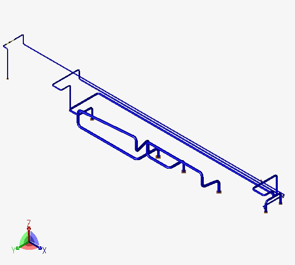
Piping layout in 3D Plant Design
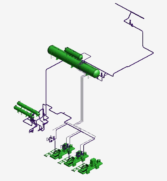
Stress model in CAESAR II
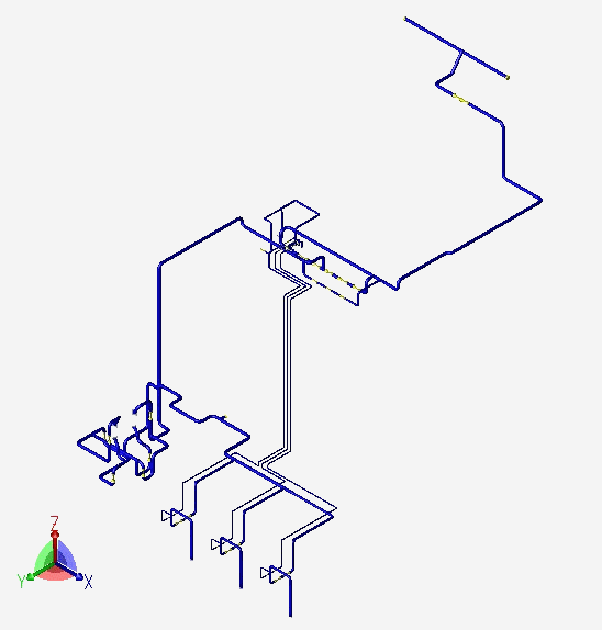
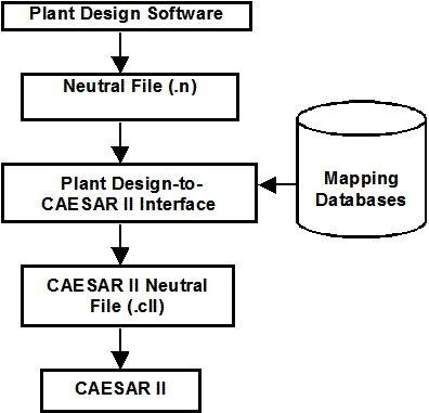
PD2CII Interface converts the 3D piping model into an intermediate neutral file. The PD2CII.exe reads this neutral file and maps it against the Material and Support Mapping DB to identify the valid CAESAR II Material and Support specifications. This executable then generates the CAESAR II neutral file. This CAESAR II neutral file is used to generate the CAESAR II Input file (*._A) that can be opened and viewed in CAESAR II.
The execution sequence is as follows.
Piping layout in 3D Plant Design
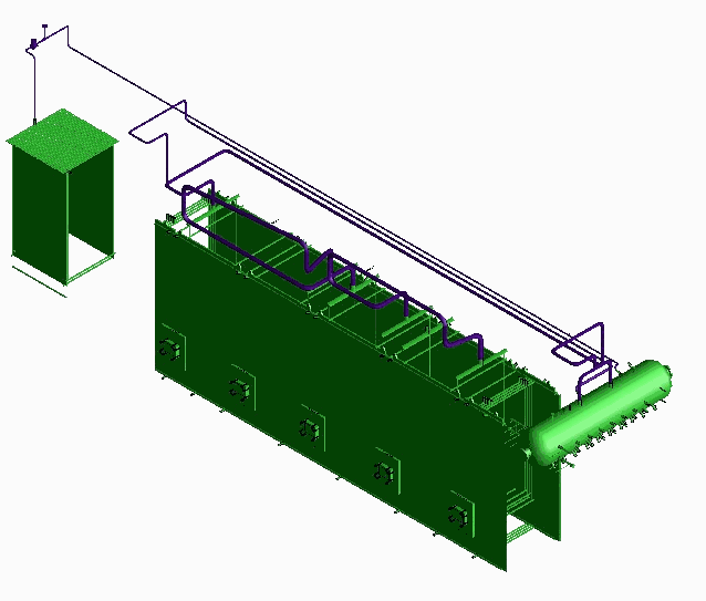
Stress model in CAESAR II
Salient Features of 3D Plant Design-to-CAESAR II Interfaces
- Uses forms and menus to input the CAEPIPE input file name and identify the branches in PDMS model to be added in the network for transferring to CAEPIPE.
- Reads and transfers the Pipe Section properties from Plant Design Database.
- Weight of fluid can be transferred to CAESAR II by defining the Specific Gravity of fluid (with respect to water) in 3D Plant Design software.
- Transfers Temperature and Pressure entered at Pipe/Branch level of 3D Plant Design software as operating loads in CAESAR II.
- Support details (entered via attributes) and their locations specified in the Plant Design software are transferred to CAESAR II. Stiffnesses, Gaps and Friction coefficients of supports can also be transferred, if defined in 3D Plant Design software.
- Transfers weight of components such as Flanges, Valves, Instruments, etc., if defined in 3D Plant Design software.
- Allows the user to choose the vertical direction in CAESAR II. Vertical direction in 3D Plant Design (Z) can be made as either 'Y' or 'Z' in CAESAR II.
